
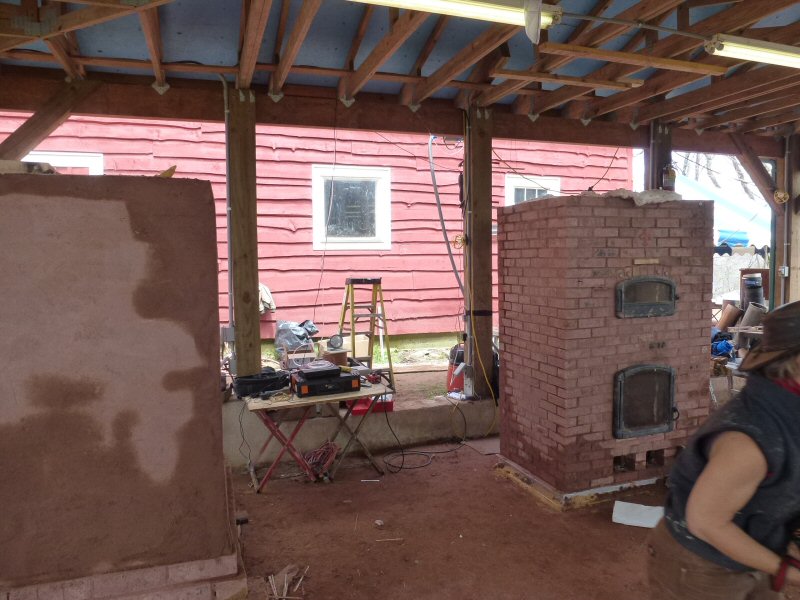
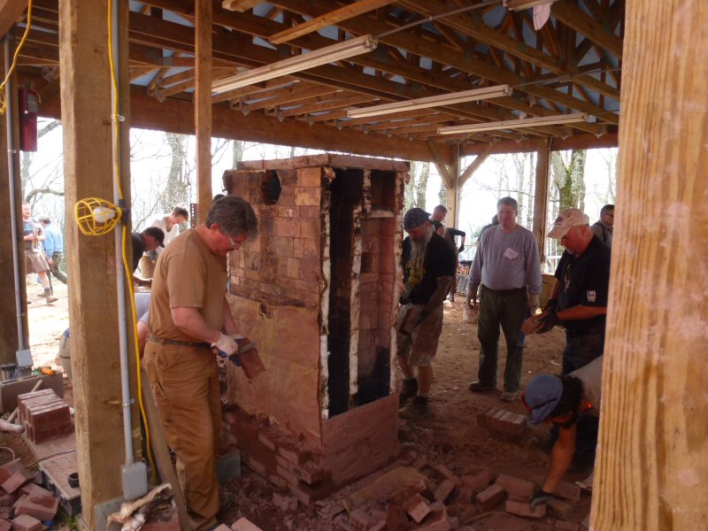
2015 MHA Annual Meeting
Heater testing workshop
with Lopez Labs Co-Operative and Damien Lehmann (Masonry Heater Association of France)
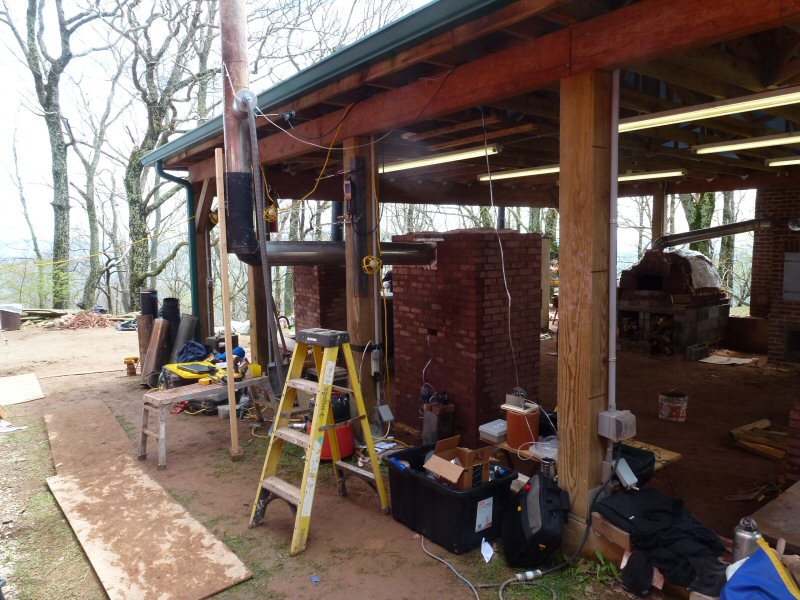
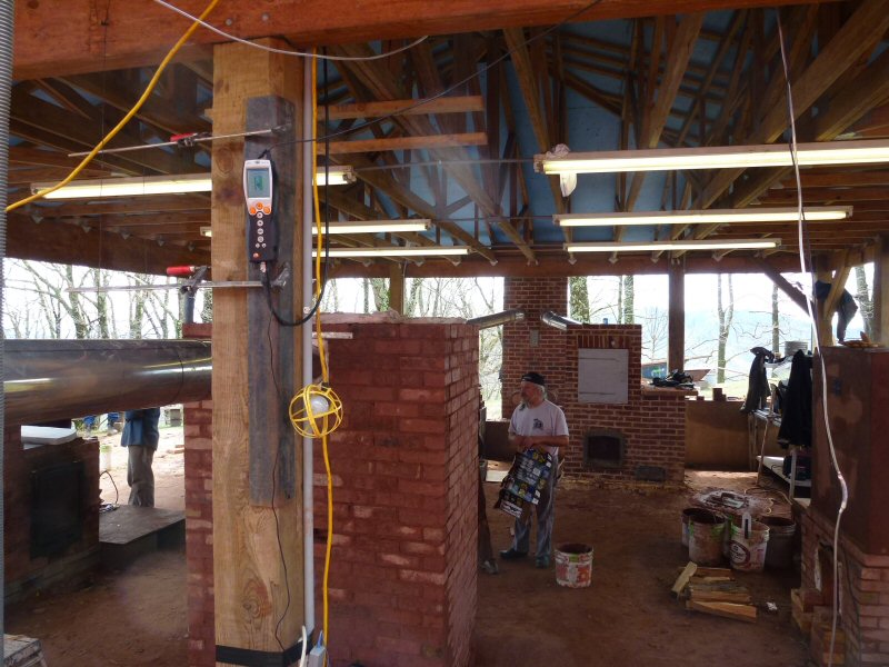
Back to Wildacres 2015 Photo Report
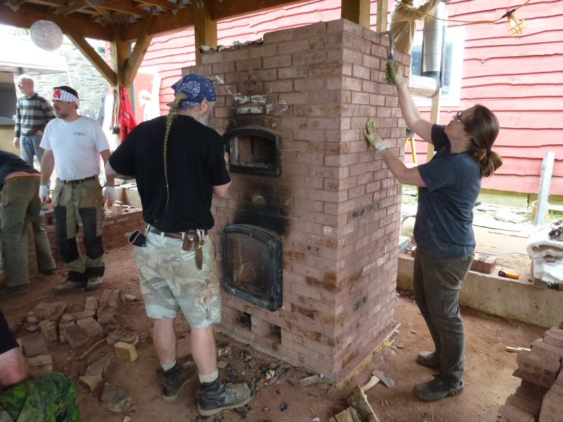
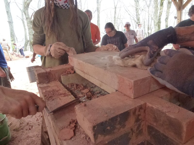
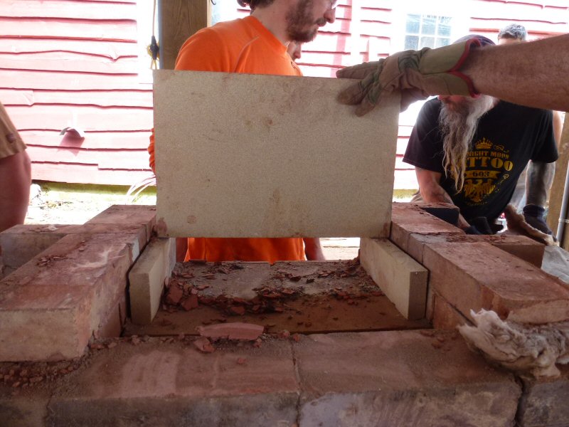
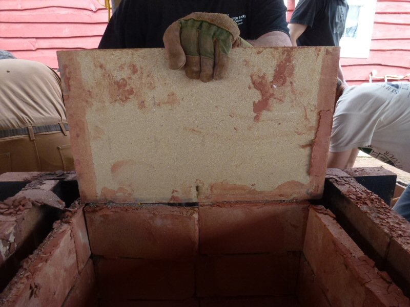
See the construction of this heater
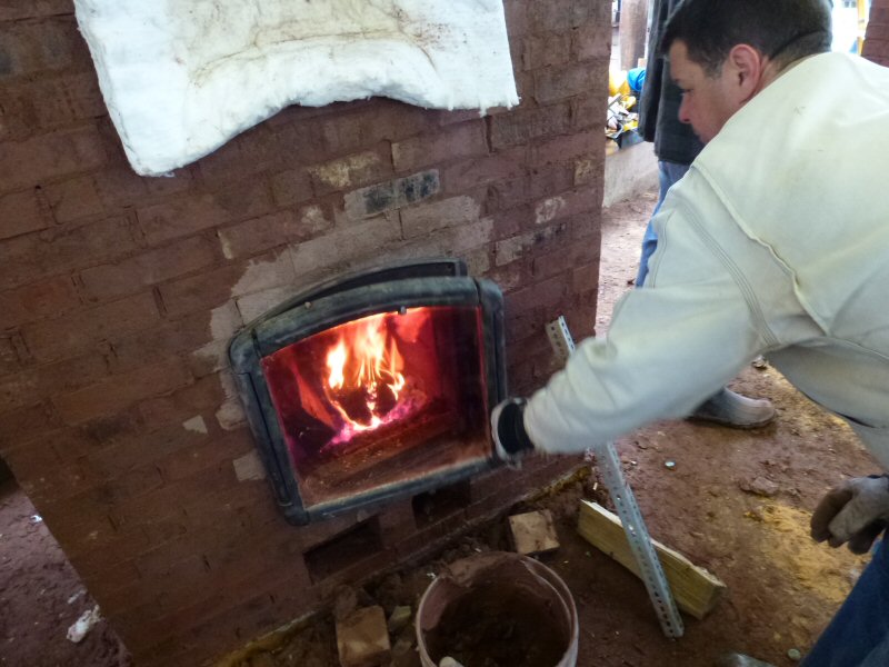
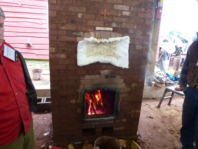
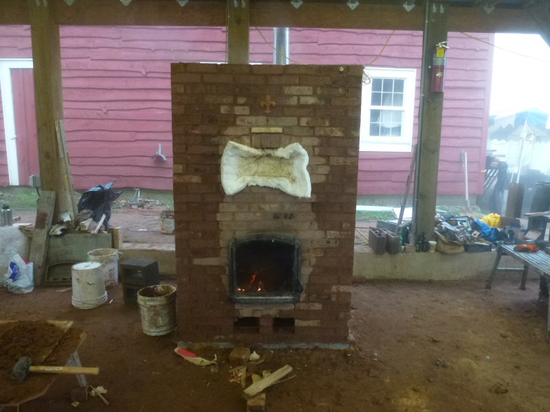
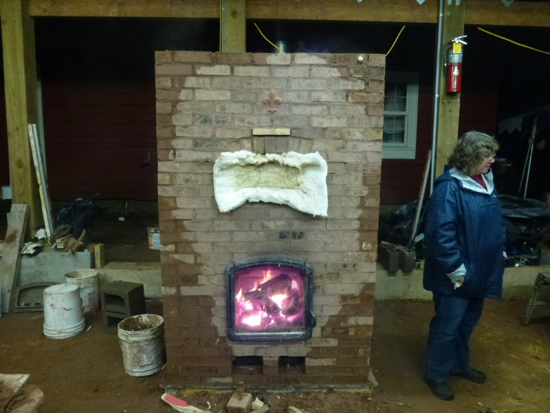
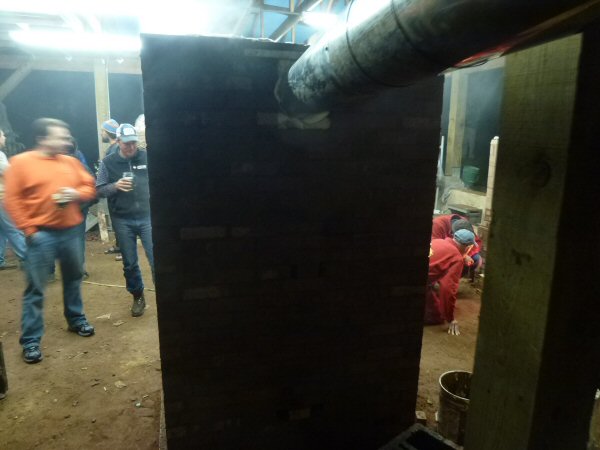
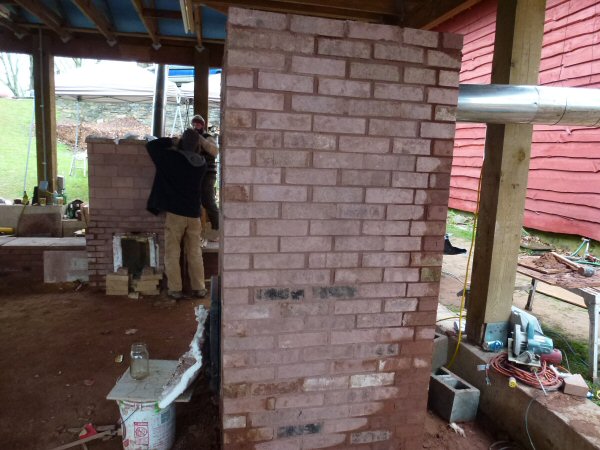
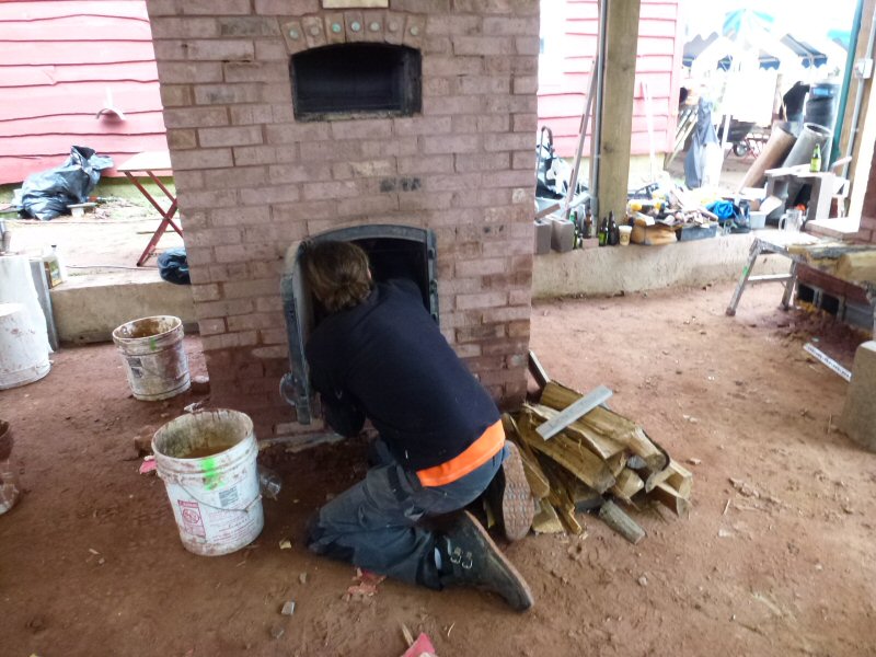
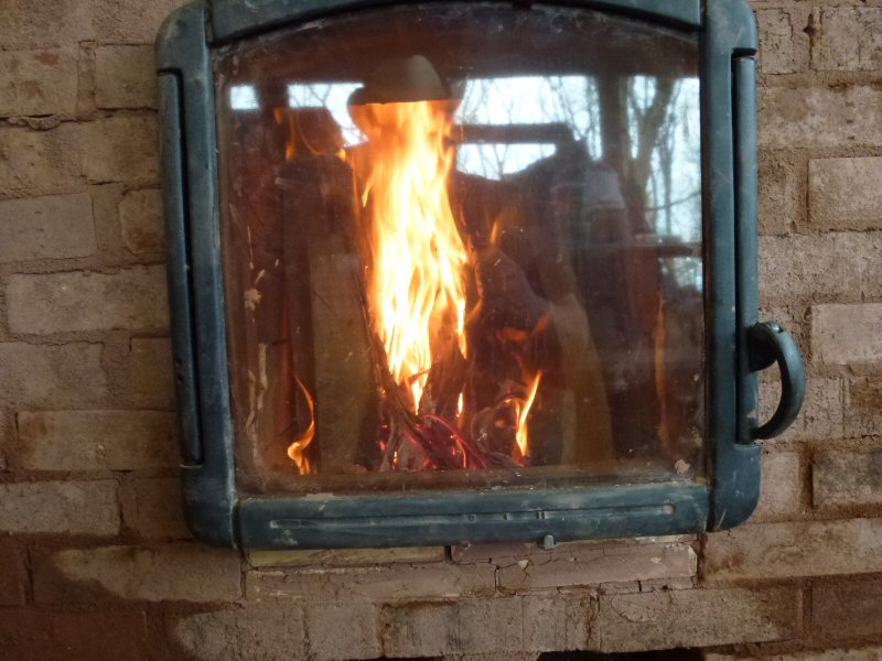
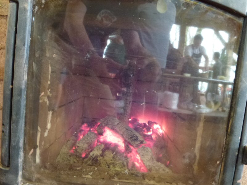
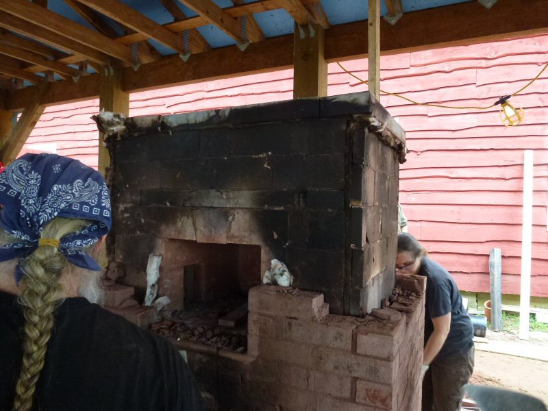
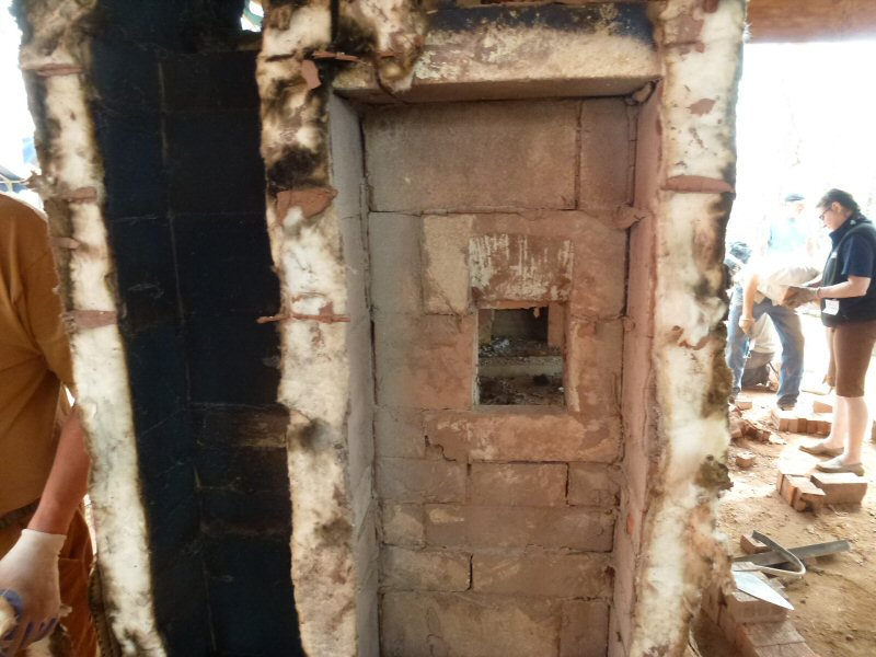
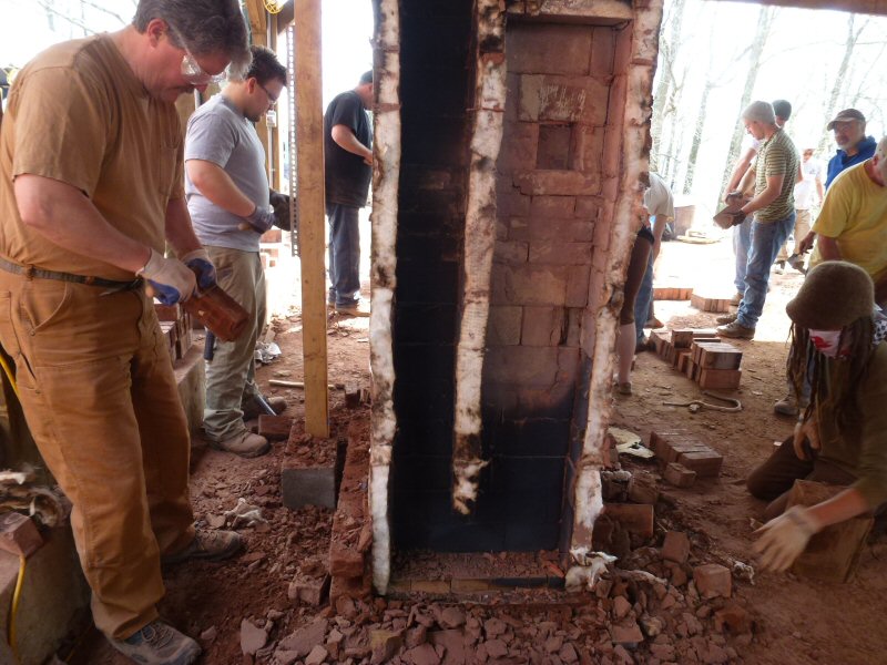
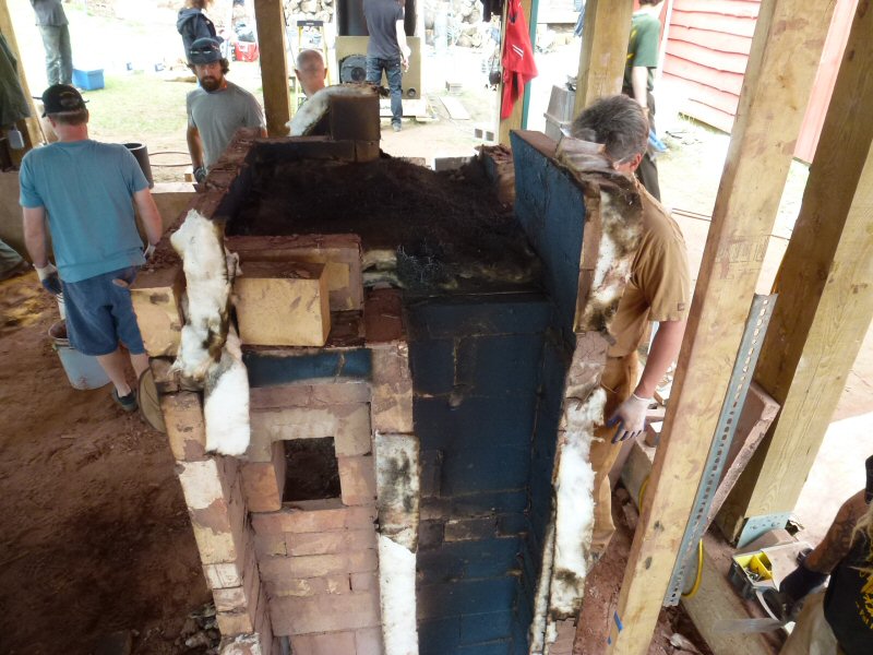
Curing fire: 4 hours
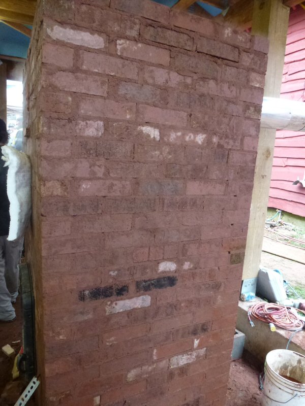
Curing fire: 4 hours, left side
Curing fire: 4 hours, right side
Curing fire: 4 hours, front.
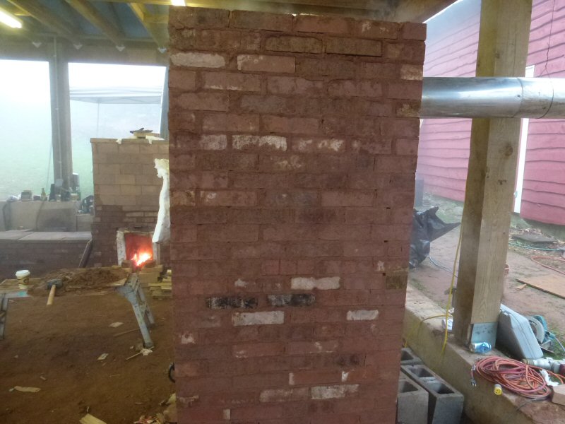
Curing fire: 5 hours, front
Curing fire: 5 hours, right side,
Curing fire 5 hours, rear.
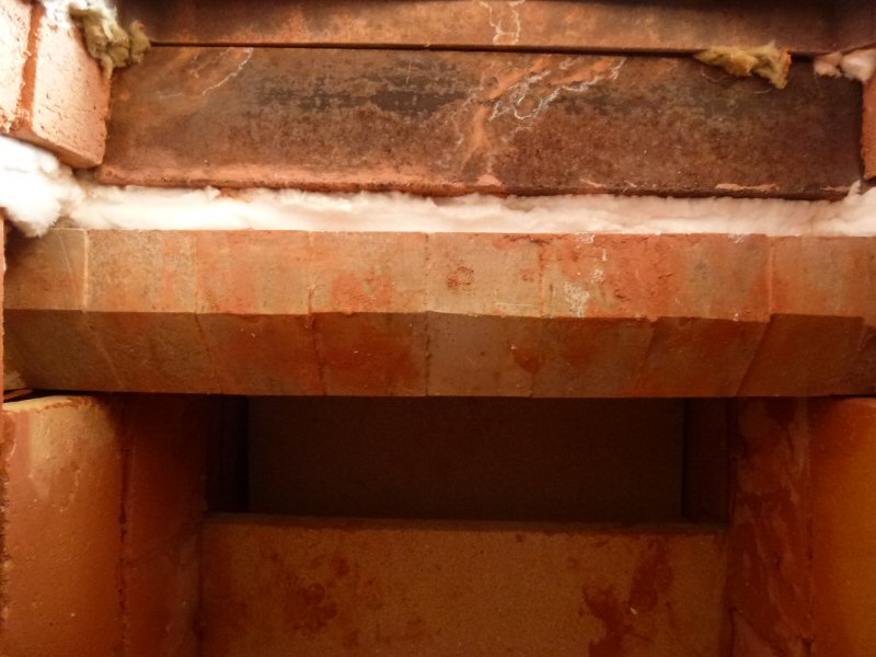
During the curing progression, note that the rear side does not dry, because of the insulated rear of the bake oven.
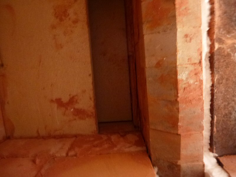
Below the bake oven, is the rear air supply separating the firebox liner from the heater facing.
Curing fire: 5 hours, left side.
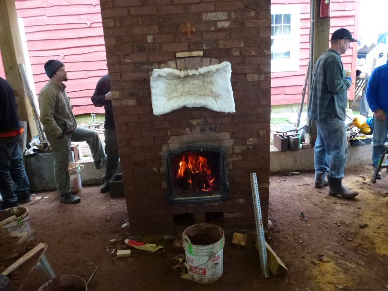
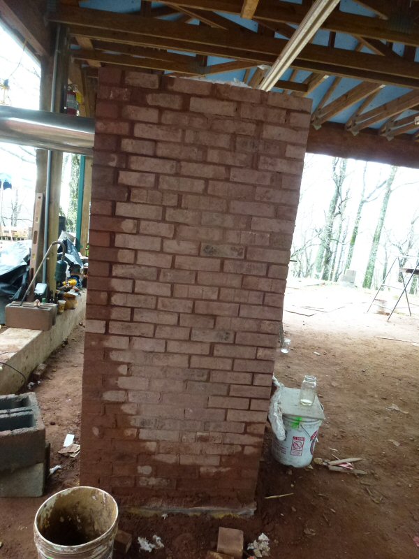
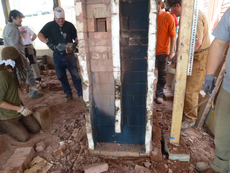
Curing fire: 6.5 hours, front
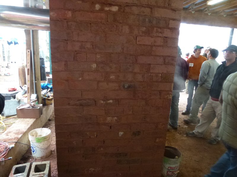
Curing fire: 6.5 hours, right side.
Curing fire: 6.5 hours, rear.
Curing fire: 6.5 hours, left side.
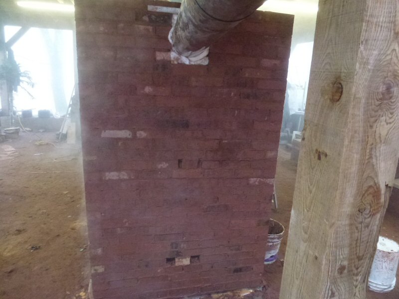
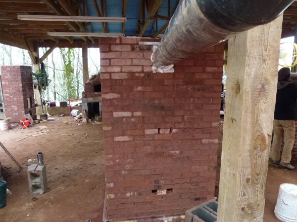
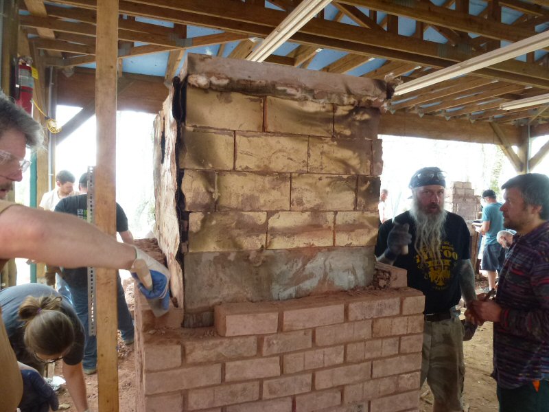
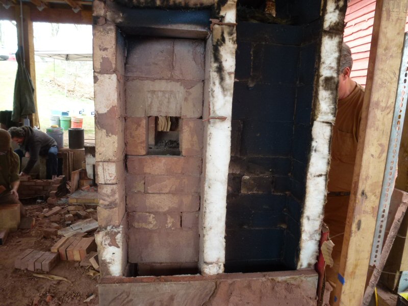
Curing fire: 11 hours. Front
Curing fire: 11 hours. Right side.
Note that the downdraft side is hotter than the updraft side, as you would expect.
Curing fire: 11 hours. Rear.
Curing fire: 11 hours, left side.
Note that, from the drying, it appears as if the left side is cooler than the right.
This is contrary to expectation if there is indeed extra heat exchange from downdrafting, since the channel divider was moved
on this side, as an experiment, to favor increas the downdrafting channel by 2.25" and reduce the updrafting channel by 2.25"
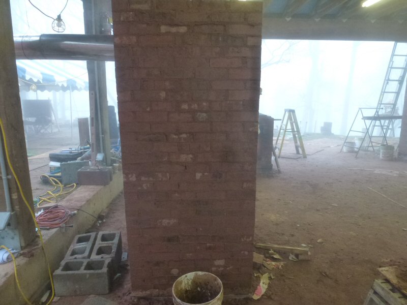
Curing fire: 12.5 hours, right side.
Curing fire, 12.5 hours, rear.
Curing fire, 12.5 hours, left side.
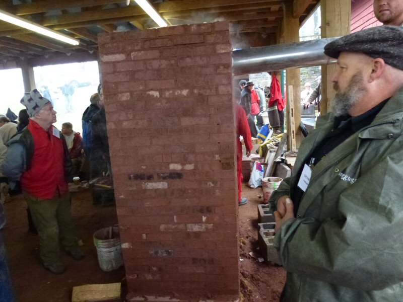
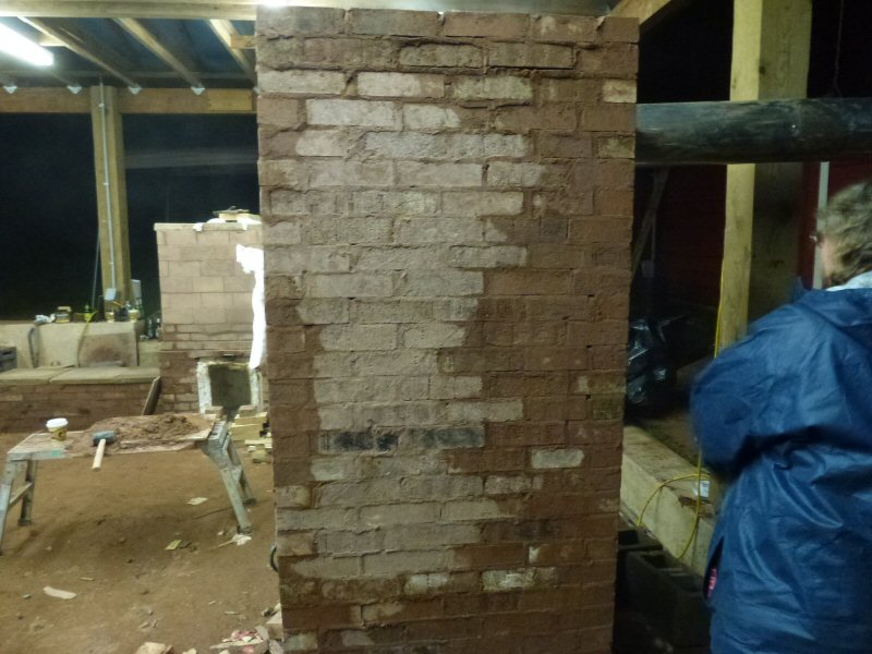
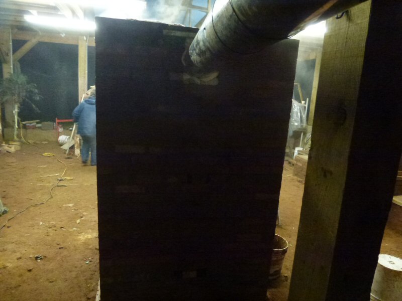
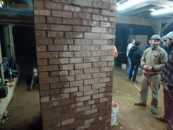
11:30 pm, Thursday night.
Friday morning 8:00 am.
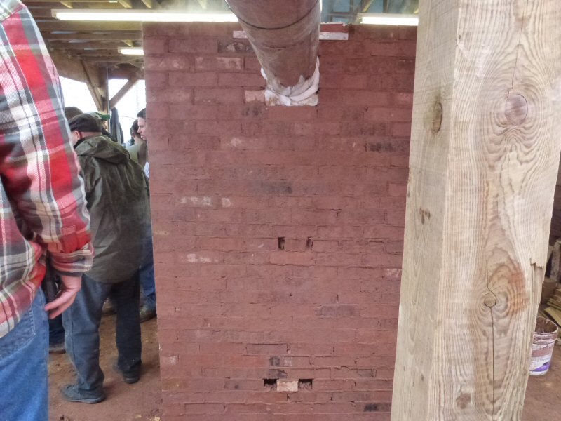
Right side, 8:00 am. 21 hours after lighting curing fire.
Rear, 8:00 am
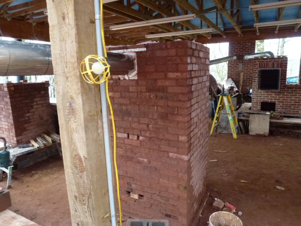
Left side, 8:00 am.
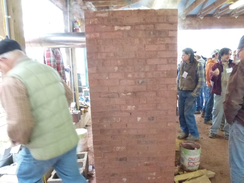
It appears to have dried less.
However, later in the day during the testing fire, an MHA member took informal readings with a
temperature gun. He reported that the downdraft side on the left ran about 20 degrees (Fahrenheit)
hotter that the right, and that at the end of the updraft run (top rear), the left side was about 9 degrees
cooler than the right. This would indicate more heat transfer from downdrafting than updrafting.
Note that on the left side, there is less drying on the updraft side, indicating cooler temperatures.
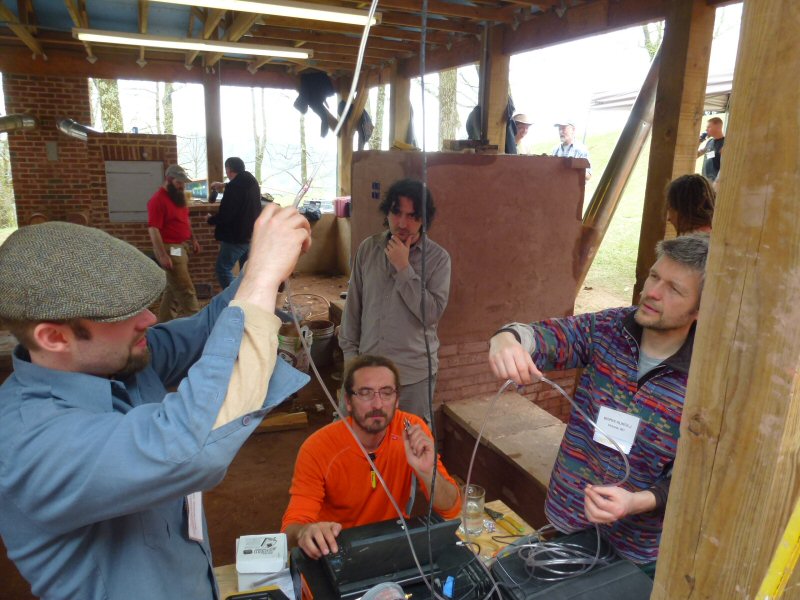
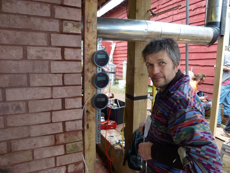
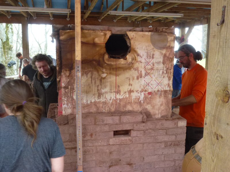
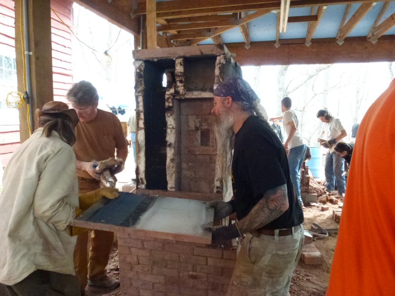
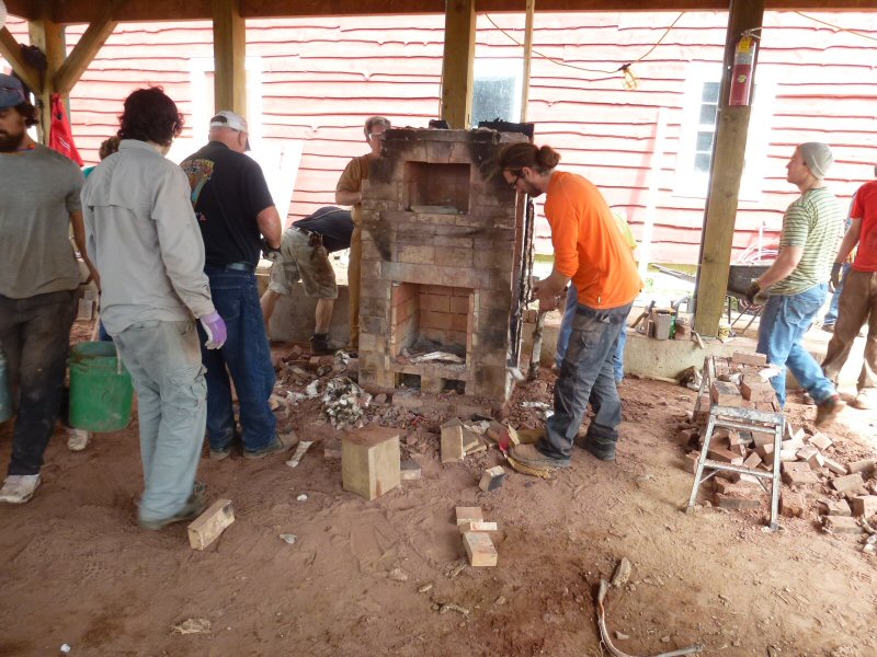
Damien Lehmann installs pressure taps at the floor and ceiling of the firebox, to measure differential pressure.
Actual results will be compared with theoretical results predicted by his calculator.
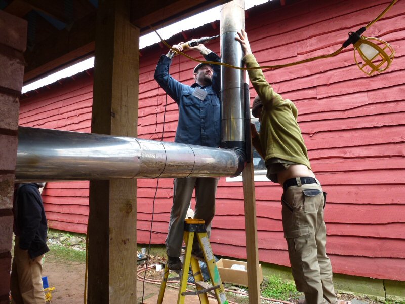
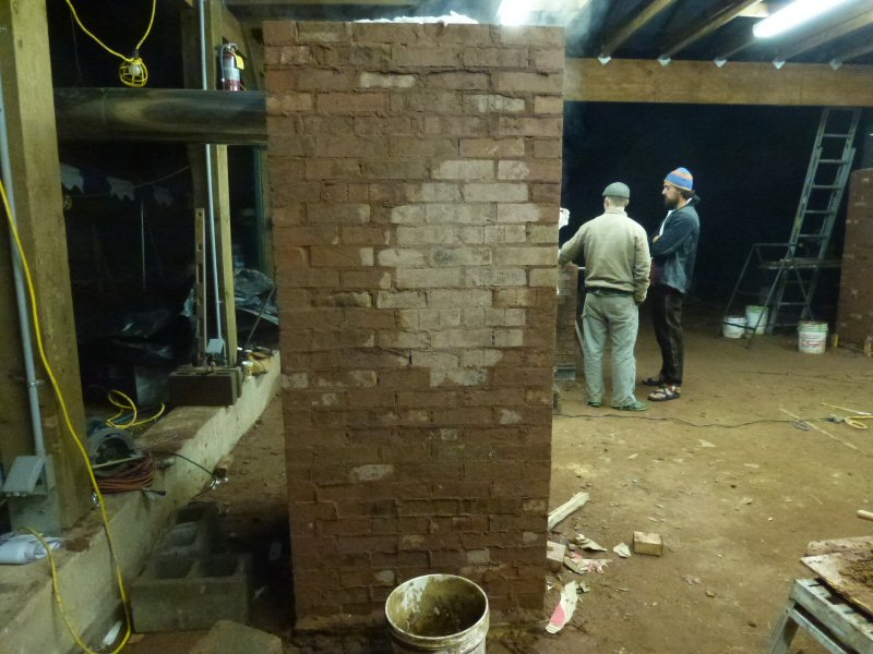
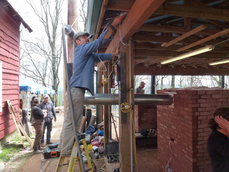
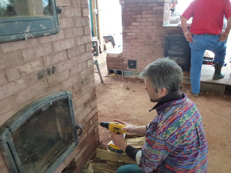
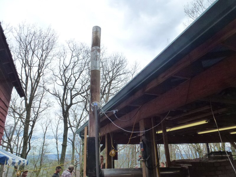
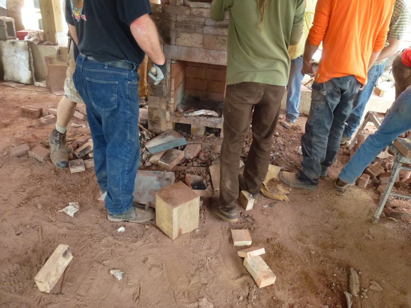
Drilling holes in the chimney for test probes for the gas analyzer and the dilution tunnel.
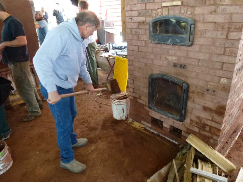
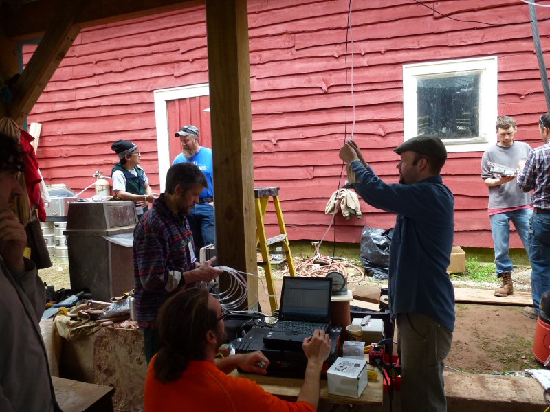
10:45 am. Time to start a cleanup for the pizza party, which starts in 4 hours.
MHA President Dan Givens pitches in.
We want to get set up and at least get the test started before the party gets into full gear.
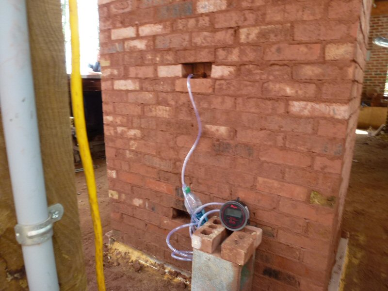
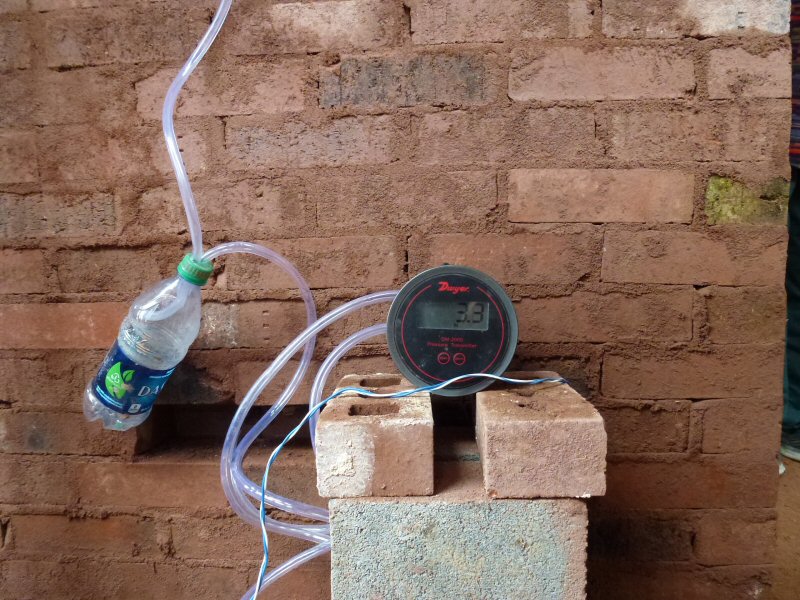
There are pressure taps at the floor and ceiling of the firebox. A differential manometer measures the pressure difference.
The empty water bottle acts to damp out pressure fluctuations.
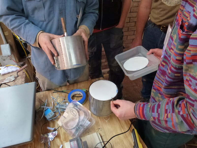
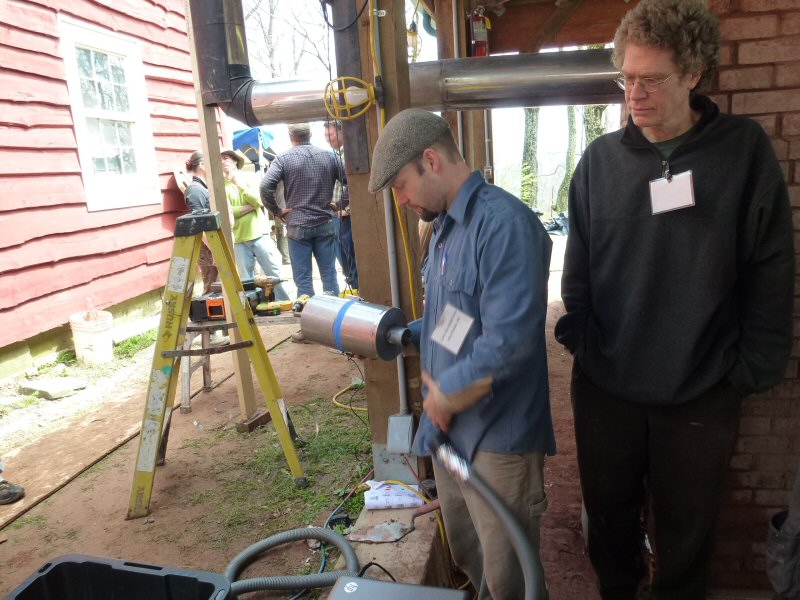
MHA's Condar portable dilution tunnel for measuring particulat emissions.
Boris Kukolj hold a moisture proof container with preweighed glass 2 micron filters.
Two of them sit back to back in the Condar.
Carsten is holding the other half of the Condar, showing the sampling nozzle that is inserted into the stack.
The
holes in the front plate provide 10:1 dilution of the stack sample with
ambient air. This allows semi-volatile tars to
condense and be measurable by the filter. This provides a near-EPA PM number.
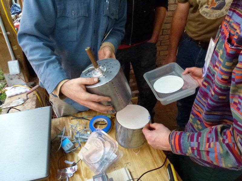
Assembled Condar, ready to mount on the stack.
The curves stainless tube coming off the sample nozzle is a pressure tap.
The pressure in the nozzle is held to a constant value, which provides constant flow (0.4 CFM) of stack sample.
Mounting a vacuum cleaner connection to the rear of the Condar.
This powers the sample collection, and draws the sample onto the filters.
As the filters load up, the vacuum needs to be increased in order to hold the flow through the sampling probe constant.
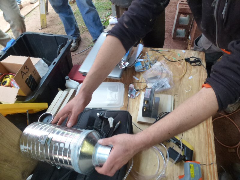
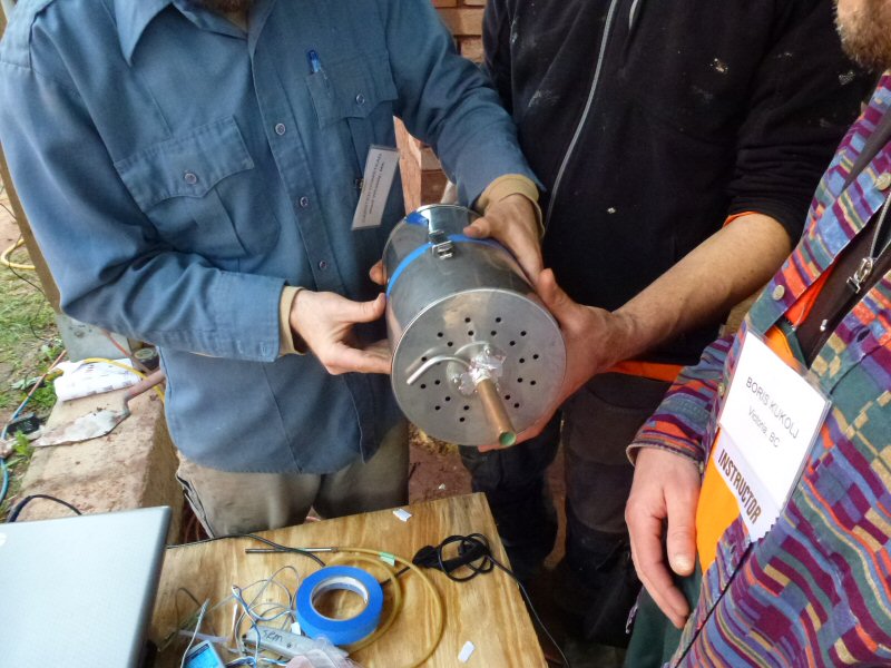
This is one of 4 new Condars that MHA recently received as a donation from Dan Givens and his fabricator friend in
Fairbanks, Alaska. It is copied from, and functionally equivalent to, the original.
I took all 4 samplers home to my lab, where I will calibrate them against an original Condar.
Carsten hooks up the pressure measurement tubing between the Condar and the control console.
The Testo 330-2 flue gas analyzer is mounted via built-in magnet, just below Carsten's left hand.
An analogue magnehelic gauge and a variable speed control are used to control the Condar. The pressure at the nozzle
pressure tap is held at a constant -12 pascals in order to provide 0.4 CFM of constant stack sample flow.
Testo 330-2
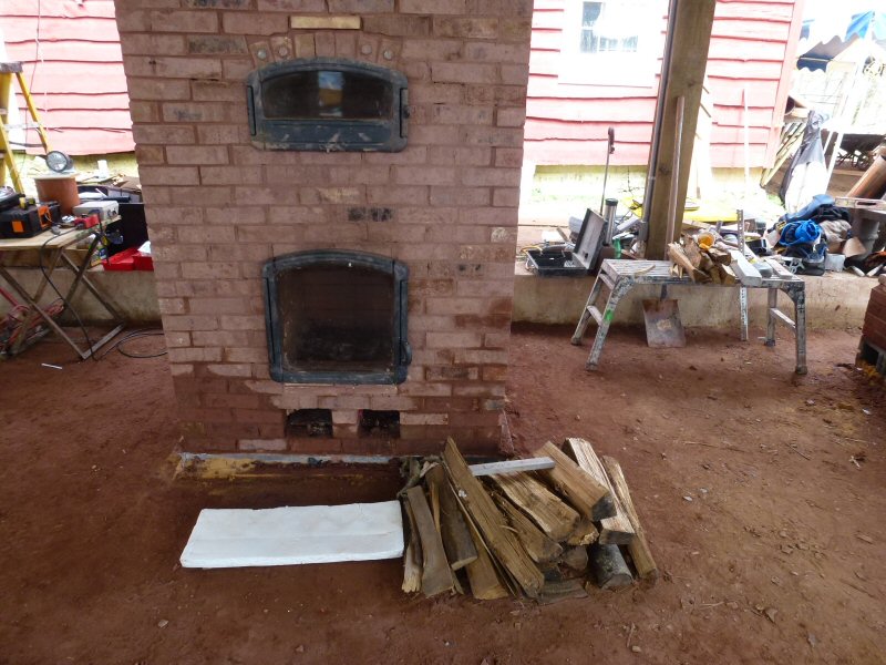
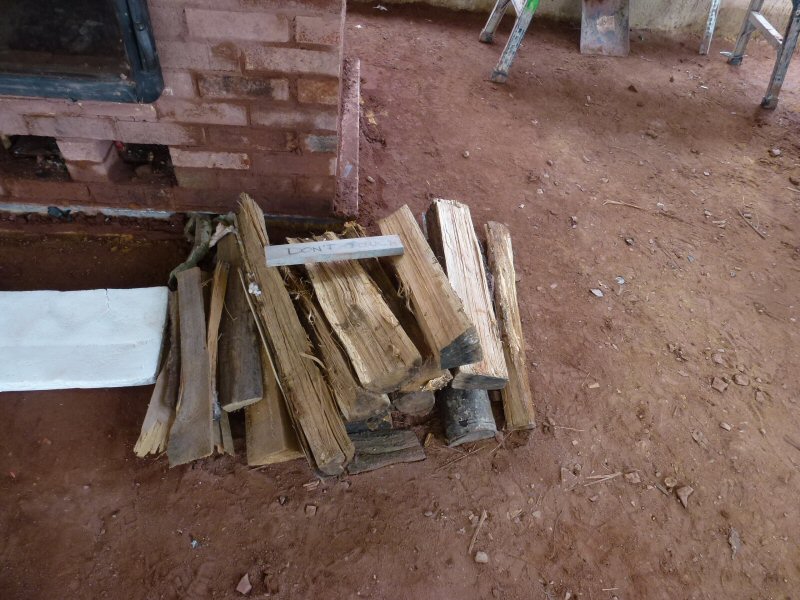
Test fuel charge. It was not weighed, as the weight is not required by the Condar spreadsheet to calculate particulates.
I selected through the limited wood supply, and picked out the driest pieces.
Some
of them were very long, and may have contributed to the slightly dirty
start, since there was too little distance for
burnout between the long pieces and the firebox ceiling.
Boris drill a hole in order to mount a pressure tap for measuring channel pressure drop.
The Testo does a live data display on the laptop, as well as providing a data file in Excel.
Andre Ferreira Luaces from Spain checks out the testing.
Andre
is an electronics specialist, and has offered to help the technical
committee with our project to automate the
operation of the Condar.
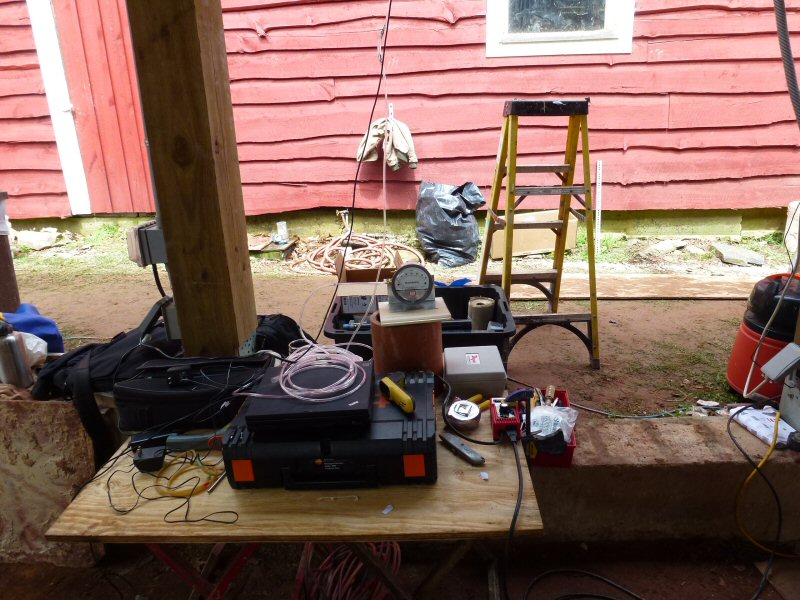
Magnehelics for measuring channel pressures.
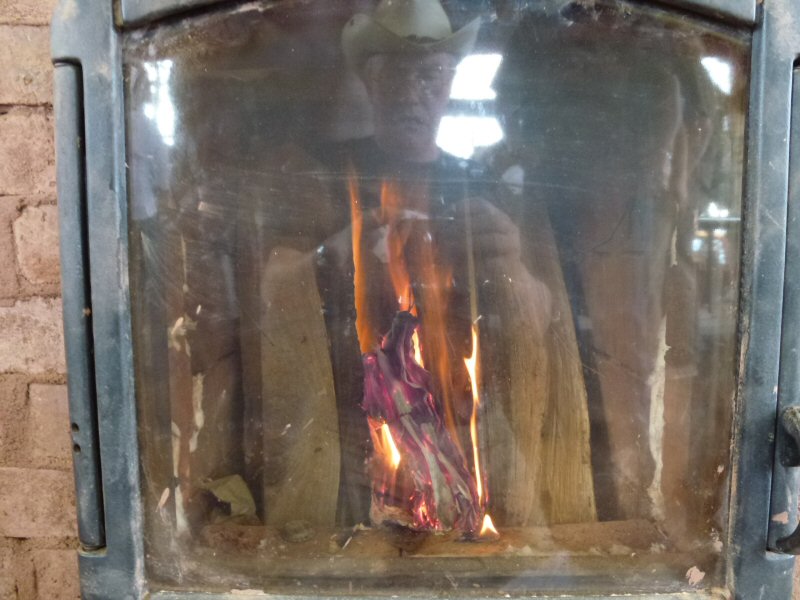
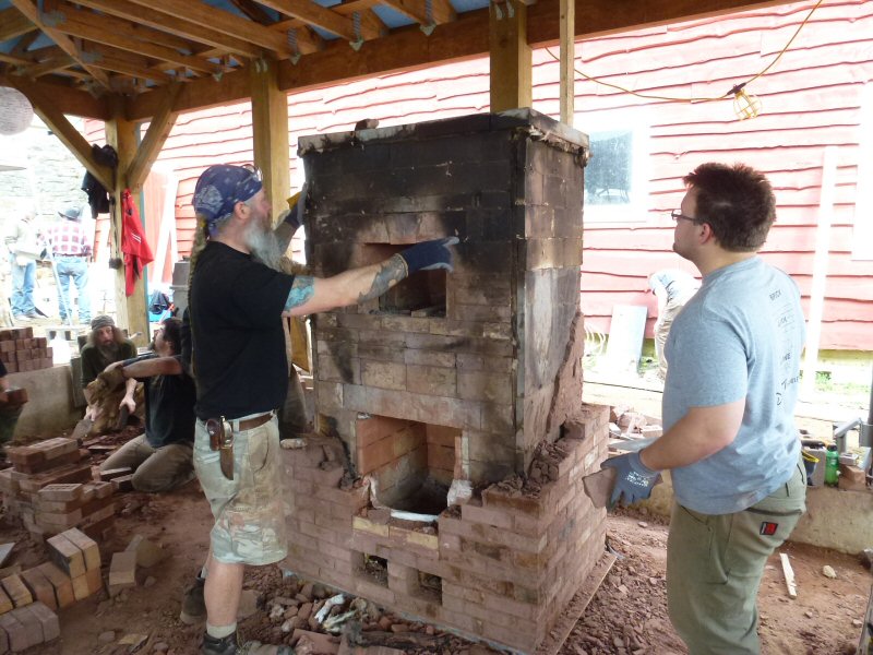
2:05 pm. Time to light the fire. Testing setup is still going on, but the Testo 330-2 and the Condar are up and running.
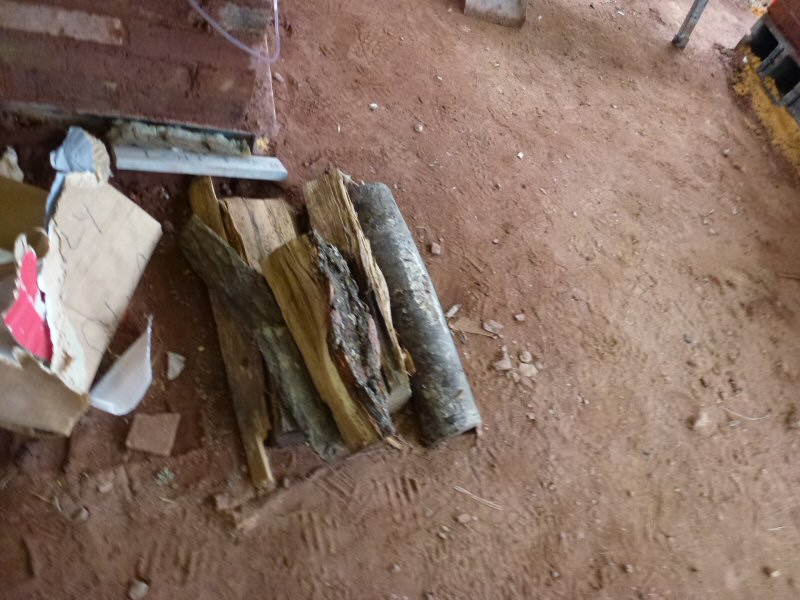
The leftover wood.
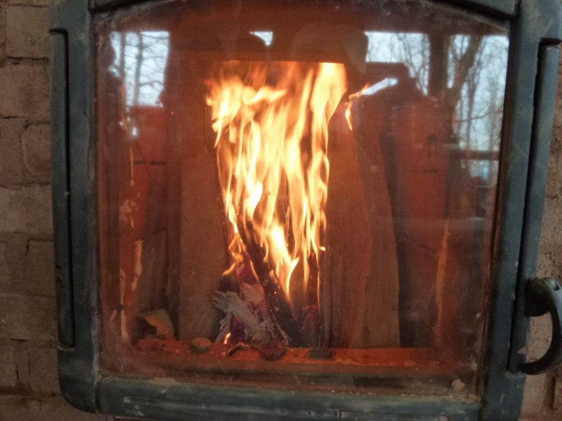
5 minutes.
Wood is stacked vertically. I have been playing with this setup in our home heater this last winter
9 minutes
stack is clear.
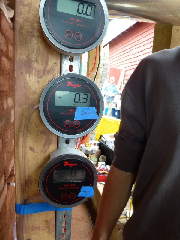
Measuring pressure differentials between the top and bottom of the channels.
This data will be used to calibrate the calculator. As it stands, the calculator is good at
predicting horizontal channels, and out by about 30% on downdrafting channels.
Measuring the temperature differential between the bottom and the top of the firebox.
The empty water bottle acts to damp out pressure fluctuations, for steadier readings.
The Dwyer Magnehelic gauge is reading in pascals. 3.3 pascals = 0.013 inches of water column
0.1 pascals, the resolution of the guage, is the difference in atmospheric pressure in about 3 vertical feet.
Atmospheric pressure is 100,000 pascals (14.7 psi).
1 hour 28 minutes.
With the Bio-firebox, the air is shut at this point, and the test is over.
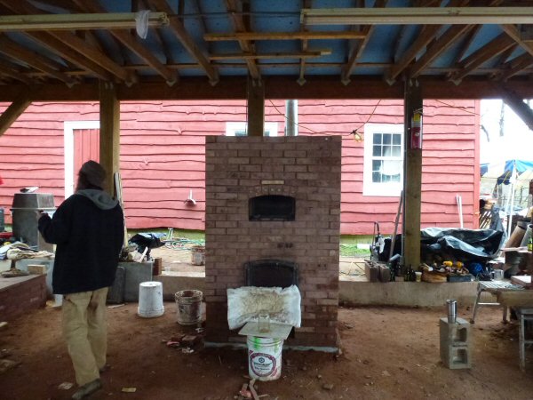
Time for a pizza party.
Oven was in the 600F range, and got a lot of use during the party.
This photo is from the next morning at 9:00 am. What happened to it last night is anybody's guess
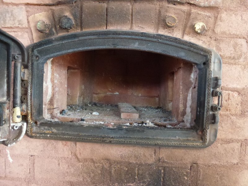
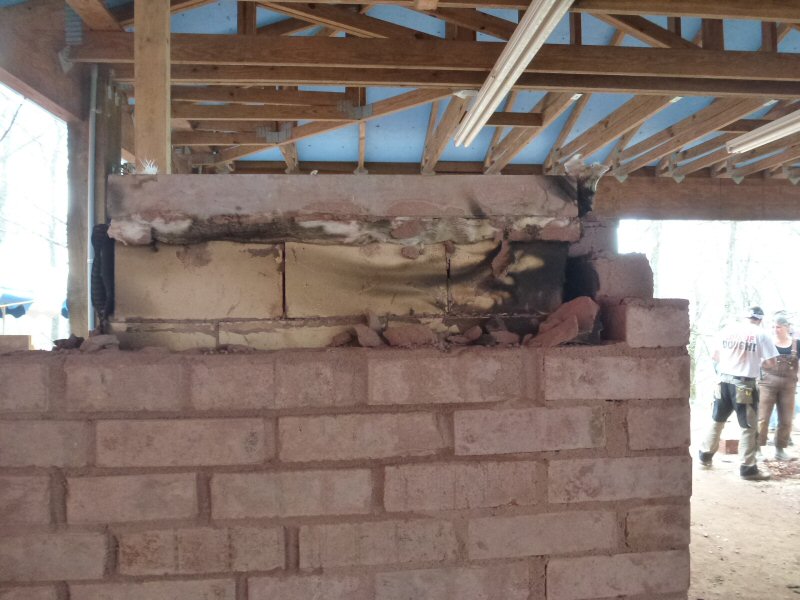
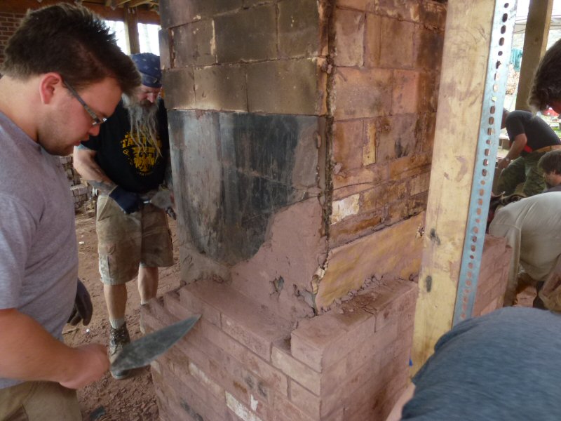
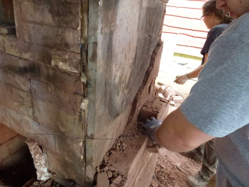
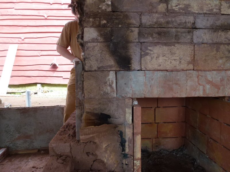
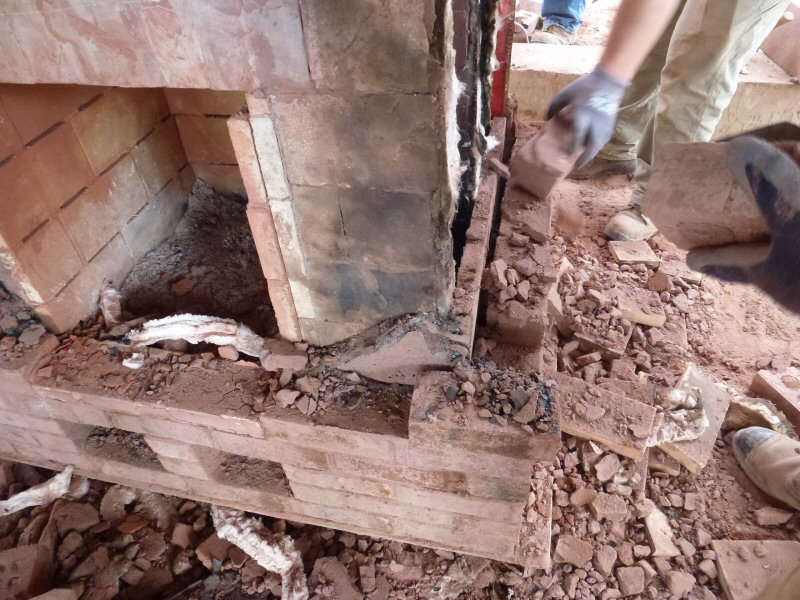
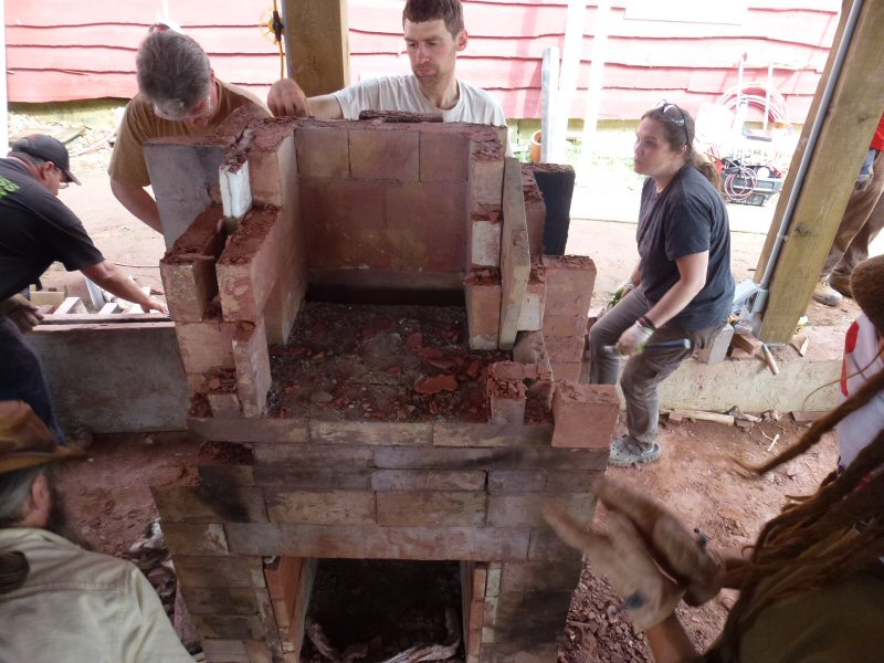
Right now it is DEMO TIME. Let's see what we can learn.
Bolted soapstone firebox lintel is on the right, and appears to be in great shape.
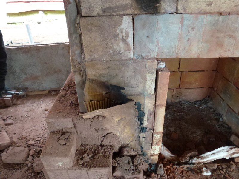
Skamolex firebox ceiling and, higher up, skamolex insulation under oven floor.
Right side.
Note the smoke leakage path.
There is no carboard against the outside of the channel, as there is already an internal expansion joint in place.
Of interest is the air tightness of the facing. Normally, mortar slush is used to make the heater tight.
In this case there may have been less slush because of the wet bricks. In this case, too much slush, when there is no brick
suction, could cause the facing to blow out. Guess how we know this.
Left side.
Note the smoke leakage path.
Smoke leakage path at the front.
The rear has cardboard.
No signs of burning, as the rear runs cool with this insulated oven design.
Note that the soapstone side panels are a tighter construction than the firebrick splits, due to fewer joints.
Good view of the slush against the right side soapstone panel.
Note the soot deposit on the updraft channel, from the super cold start with so-so wood of the wrong length.
We have not done controlled testing with vertical stacking with the Bio-box yet, so don't know if that is also a factor.
Left side. Note that the downdraft channel got hot enough to burn off the soot.
Right side.
Burned cardboard at the front.
One outstanding question is whether the burned out cardboard creates a gap that can provide a leakage path.
Also, one often sees buckled cardboard that is not lying flat against the core, which can create additional voids.
Left side.
Note the height at which the clean zone transitions to soot.
Right side.
Note that the soot is 1 course (4.5") lower, indicating a hotter channel, ie., less heat exchange.
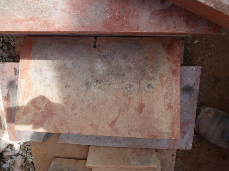
Insulation above the oven ceiling.
Note the broken soapstone slab. It was still unexpectedly hot when picked up with work gloves, and had to be dropped.
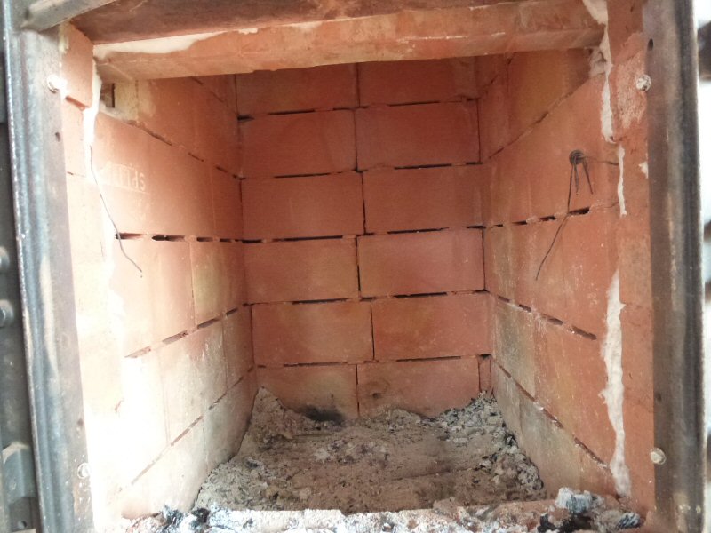
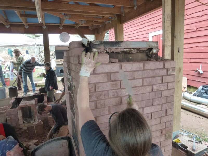
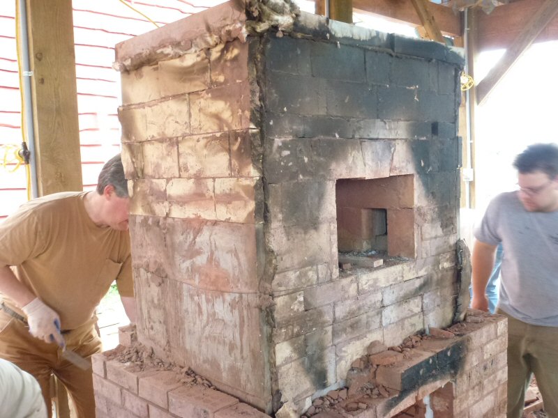
Dismantling the oven and checking the condition of the Skamolex panels.
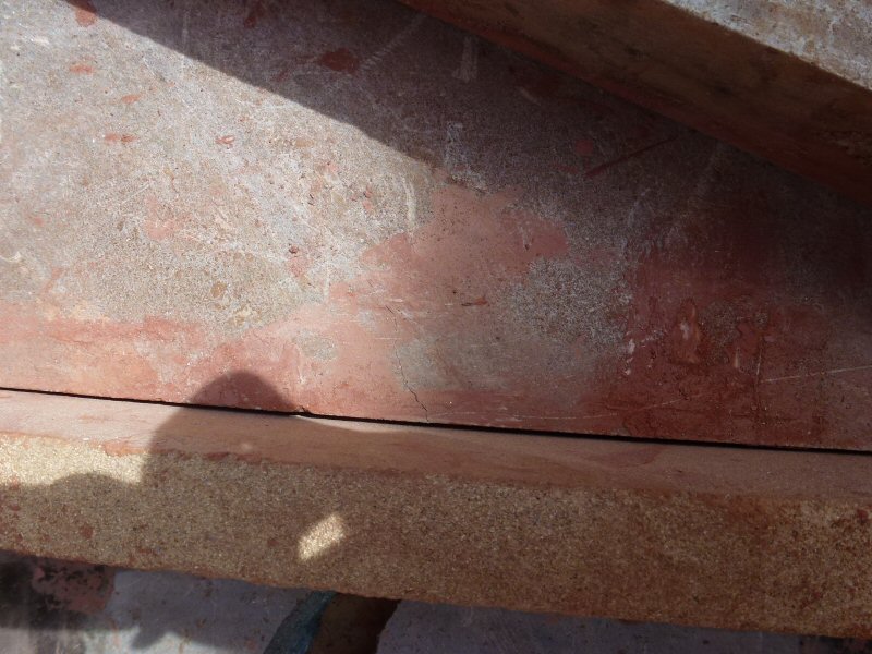
Firebox ceiling looks perfect.
Sighting down the edge of the firebox ceiling. No detectable deflection.
Sighting down the ceiling edge.
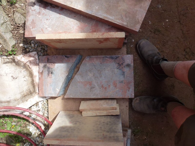
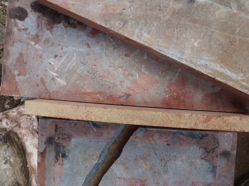
Hairline crack in one of the bake oven slabs, likely the ceiling.
Check back for test results, once we have them worked up.
See also:2014 Photo Report
2013 Photo Report
2012 Photo Report
2011 Photo Report
2010 Photo Report
2009 Photo Report
2008 Photo Report
2007 Photo Report
2006 Photo Report
2004 Photo Report
2003 Photo Report
2002 Photo Report
2001 Photo Report
2000 Photo Report
1999 Photo Report
1998 Photo Report
1997 Photo Report
This page was last updated on April 24, 2015
This page was created on April 23, 2015
Back to: